battalion51
Engineer
Brake Pipe and Main Reservoir.


So: pressure gauges?Brake Pipe and Main Reservoir.
Quite impressive.A little over 2 minutes and that unit hit 100MPH. That's impressive!
On the 2nd video, can anyone make sense/explain the other "gauges" on the display - the speedo is obvious - but what are the others showing? Per chance is the far left bar graph current incoming off the lines [even when I full-screen and stop the vid, trying to read units or titles is about impossible]. Anyone with a better understanding of what needs to be displayed, and better eyes would help. Also, how/where was the 125mph limit/desired speed set/programmed in? Or was that done by hand in realtime?
as always: many thanks - greg
I can answer two of your questions:JIS - as always - a man that knows his topic. Thank you.
The traction force I presume is in 1,000 ft lb units, ie, the max for the acs-64 is 72k ftlb, and it the bar graph is marked as 10, 20, 30... 70, 80 - that would fit?
On the traction force gauge - there is the bar graph - which I assume is the currently applied force, but there is a triangular pointer on its left side - possibly some software perception of what the current condition will permit? Or maybe an operator set desired value?
On the acceleration horizontal bar graph - any guess as to the units? In milli-G's? fps^2 or mps^2? ... but none seem to fit the digital readout associated with the bar graph.
I assume the "alerter" is effectively an old world "dead-man switch" ?
again, many thanks - greg
Fan Railer - many thanks for the posting/reply - clearly by someone that know of which he speaks.I can answer two of your questions:JIS - as always - a man that knows his topic. Thank you.
The traction force I presume is in 1,000 ft lb units, ie, the max for the acs-64 is 72k ftlb, and it the bar graph is marked as 10, 20, 30... 70, 80 - that would fit?
On the traction force gauge - there is the bar graph - which I assume is the currently applied force, but there is a triangular pointer on its left side - possibly some software perception of what the current condition will permit? Or maybe an operator set desired value?
On the acceleration horizontal bar graph - any guess as to the units? In milli-G's? fps^2 or mps^2? ... but none seem to fit the digital readout associated with the bar graph.
I assume the "alerter" is effectively an old world "dead-man switch" ?
again, many thanks - greg
Firstly, the triangular pointer on the TE bar signifies how much TE is commanded by the current throttle setting (also factoring in current speed). Whether or not the blue bar (signifying actual TE) reaches the command triangle depends on adhesion conditions. You can clearly see in the video that for the low speed acceleration part, wheel slip does occur, and if you watch in HD, you can see the wheel slip indicator pop up on the screen.
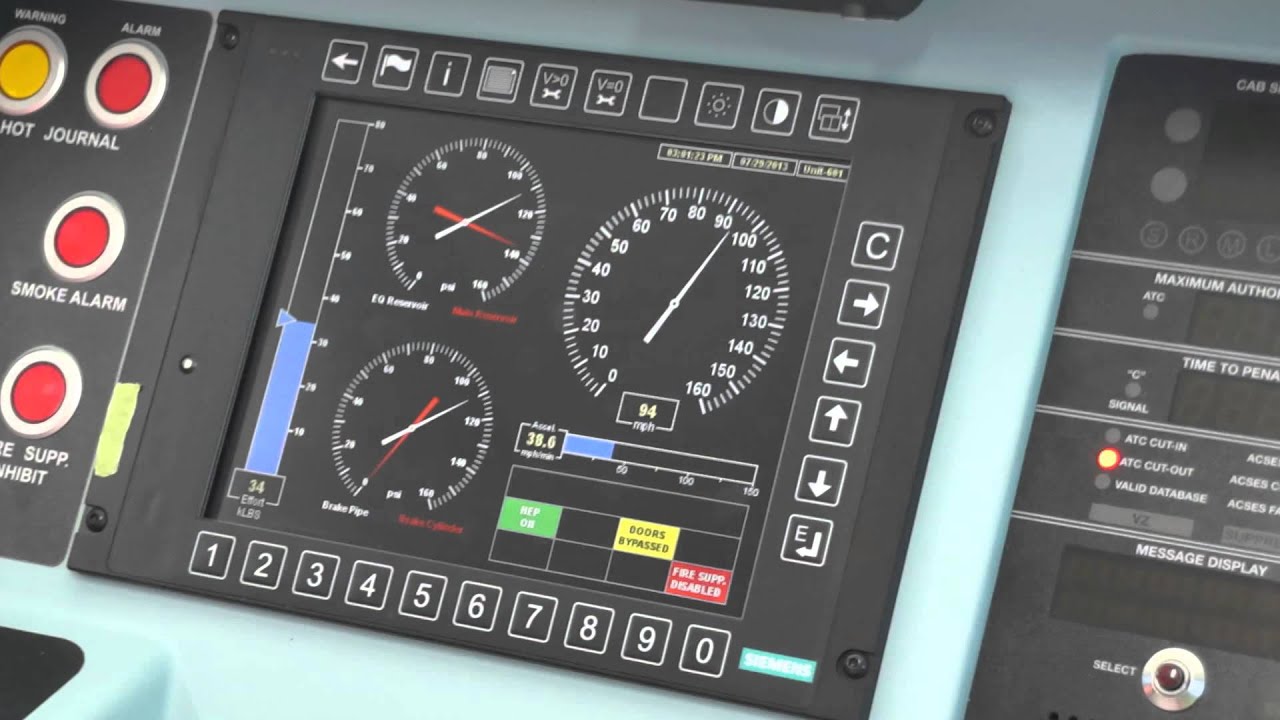
Secondly, the accelerometer is measured in units of "miles per hour per minute." Once again, if you watch in HD and full screen, you can make it out. I will also post a popular high resolution image here of the cab display courtesy of the same video. Perhaps you will be able to make it out better:
In the video, I am guessing that the throttle is only at around 90%. Addressing the wheel slip issue, yes, the locomotive's software is limiting tractive effort as it detects wheel slip. Remember that this is one of the test locomotives at Pueblo, so I doubt any sort of limitation is applied to the amount of power that the locomotive will provide given the maximum throttle setting.Fan Railer - many thanks for the posting/reply - clearly by someone that know of which he speaks.I can answer two of your questions:JIS - as always - a man that knows his topic. Thank you.
The traction force I presume is in 1,000 ft lb units, ie, the max for the acs-64 is 72k ftlb, and it the bar graph is marked as 10, 20, 30... 70, 80 - that would fit?
On the traction force gauge - there is the bar graph - which I assume is the currently applied force, but there is a triangular pointer on its left side - possibly some software perception of what the current condition will permit? Or maybe an operator set desired value?
On the acceleration horizontal bar graph - any guess as to the units? In milli-G's? fps^2 or mps^2? ... but none seem to fit the digital readout associated with the bar graph.
I assume the "alerter" is effectively an old world "dead-man switch" ?
again, many thanks - greg
Firstly, the triangular pointer on the TE bar signifies how much TE is commanded by the current throttle setting (also factoring in current speed). Whether or not the blue bar (signifying actual TE) reaches the command triangle depends on adhesion conditions. You can clearly see in the video that for the low speed acceleration part, wheel slip does occur, and if you watch in HD, you can see the wheel slip indicator pop up on the screen.
Secondly, the accelerometer is measured in units of "miles per hour per minute." Once again, if you watch in HD and full screen, you can make it out. I will also post a popular high resolution image here of the cab display courtesy of the same video. Perhaps you will be able to make it out better:
With your hi-res image in fact I was able to read what you pointed out - again, thanks.
A question about wheel slip - clearly unbridled wheel slip is rough both on the rails and the engine - the fact that the bar graph shows a value less than the commanded value - is that simply raw slip which is limiting what is applied and the drive wheels are slipping significantly; or is there software, much like an ABS unit in a car, but in reverse, putting down as much TE as the situation will allow, in attempt to save both rails and engine, ie, walking the edge of adhesion, but putting down/out no more torque than that? Related: if I read correctly, the -64 is capable of 72kftlb TE, but the highest commanded value I see is in the 64-65k range - is that a result of restraint on the engineer's part, or have the throttles been "detuned" and "100%" is derated to that 65k level?
again, many thanks for the much better image and thanks for the answers - greg
")
Btwn you and Fan Railer, lots of leaning to be had - many thanks to both of you... as much as I like riding trains, have spent too many years as a lab scientist to not ask (need to ask??) the how and why questions. ;-) ;-(Greg, a radar unit is used to calculate actual linear speed of the engine. From that you can compute what the wheel rotation speed should be. If it is higher than that beyond a threshold then the Wheel Slip Management unit will take appropriate action to bring down the angular speed of the wheel to match that as computed from the linear velocity of the engine. These units have become extremely sophisticated and able to pretty much apply the absolute maximum torque/tractive effort just below wheel slip. Usually when they are active and running at the edge, you will hear an occasional screeching noise even on straight track.
The radar is in the same band as police radar in some cases so it is kind of fun to watch those over-speeding on parallel roads depending on their radar detectors.
BTW, even putting the throttle at 100% would not cause it to go any faster since the wheel slip management would intervene anyway.
And yes each axle is driven independently, though I believe each truck has a single set of inverters driving them, though I could be wrong.
With the Prius, using a micropower radar makes perfect sense, ie, looking for large highly microwave reflective objects with clean signatures... but with a train with so much clutter around, seems like a hit or miss proposition. Any idea when they went to radar for speed determination (era wise) - that might offer some hints as to why?I believe radar is used because it is a nice cheap self-contained unit. Heck My Prius uses a little radar to measure distance from and speed of the car ahead of me to modulate the speed of the cruise control to match that of the car ahead of me, to maintain the distance from it that I set through controls on the steering wheel.
Many thanks for the post - truly easy to read all the controls and labels... when one can actually read stuff, one can find answers ;-)If people want an even closer look, this was posted on Amtrak's blog (link to a huge picture).
Enter your email address to join: